Industrial Automation
 Available

 Available
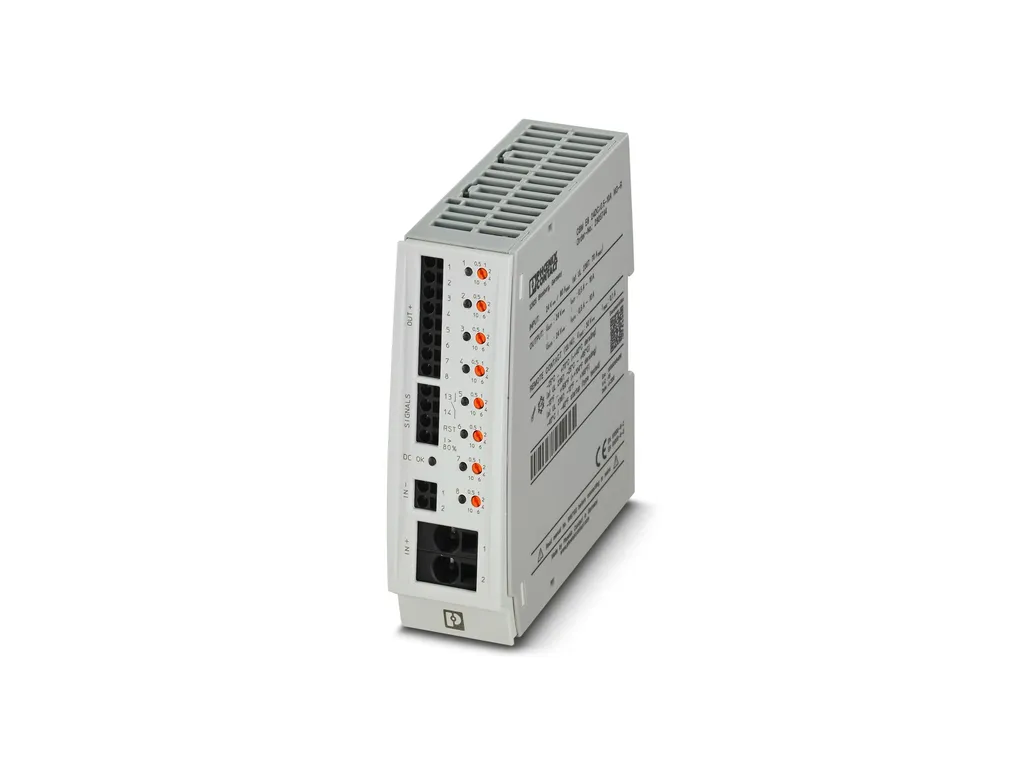
 | Product properties | Type: DIN rail module, one-piece Product type: Device circuit breakers Product family: CBM Number of positions: 1 No. of channels: 8 Insulation characteristics Protection class: III Pollution degree: 2 |
| Electrical properties | No. of channels: 8 General Operating voltage: 18 VÃDC ... 30 VÃDC Rated voltage: 24 VÃDC Rated current IN: max. 80 AÃDC (for double supply IN+ with at least 2 x 6 mm²) max. 70 AÃDC (for UL 2367) 0.5Ã/Ã1Ã/Ã2Ã/Ã4Ã/Ã6Ã/Ã10ÃAÃDCÃ(adjustable per output channel) Rated current (pre-adjusted): 0.5 A Rated surge voltage: 0.5 kV Tripping method: E (electronic) Feedback resistance: max. 35 VÃDC Required backup fuse: Only required if Imax of the power supply > the short-circuit switching capacity. Integrated failsafe element. Short-circuit switching capacity: 300 A Dielectric strength: max. 30 VÃDC (Load circuit) Active current limitation: typ. 1.5 x IN (2 - 10 A) Fuse: electronic Efficiency: > 99 % Closed circuit current I0: typ. 50 mA Power dissipation: 1.2 W (No-load operation) 17.2 W (Nominal operation) Module initialization time: 3.3 s Waiting time after switch off of a channel: 10 s (at overload / short circuit) Measuring tolerance I: typ. 40 % (0.5ÃAÃ...Ã1ÃA) typ. 10 % (2 - 10ÃA) Temperature derating: 40 AÃDC (at 70°CÃ(65°C for UL 2367)) 50 AÃDC (at 60ðC) 60 AÃDC (at 50ðC) 70 AÃDC (at 40ðC) 80 AÃDC (at 40ðC) 70 AÃDC (at 40°C for UL 2367) MTBF (IEC 61709, SN 29500): 1304293 h (at 25ðC) 858501 h (at 40ðC) 440048 h (at 60ðC) Fail-safe element: 15 AÃDC (per output channel) Load circuit Shutdown time: 0.02 s (> 1.3 x IN) 30 s (1.1 ... 1.3 x IN) Undervoltage switch-off: ââ°¤ 17.8 VÃDC (active) ââ°¥ 19 VÃDC (inactive) Overvoltage switch-off: ââ°¥ 30.5 VÃDC (active) ââ°¤ 29.5 VÃDC (inactive) Max. capacitive load: 75000 õF Reset Input voltage range: 7 VÃDC ... 30 VÃDC (Reset with falling edge) Current consumption: typ. 0.4 mA (at 24 V DC) Pulse length: ââ°¥ 50 ms (High signal) ââ°¥ 50 ms (Low signal) Voltage: < 5 VÃDC (Low signal) > 8 VÃDC (High signal) Status output Output voltage: 24 VÃDC Output current: max. 20 mA (when I > 80%Ãat at least one channel) Indicator/remote signaling Connection name: Remote indication circuit Switching function: N/O contact Operating voltage: 0 VÃDC ... 30 VÃDC Operating current: 1 mA DC ... 100 mA DC |
| Connection data | Main circuit IN+ Connection method: Push-in connection Stripping length: 18 mm Conductor cross section rigid: 0.75 mm² ... 16 mm² Conductor cross section AWG: 20 ... 4 Conductor cross section, flexible, with ferrule, with plastic sleeve: 0.75 mm² ... 10 mm² Conductor cross section flexible, with ferrule without plastic sleeve: 0.75 mm² ... 16 mm² Main circuit IN- Connection method: Push-in connection Stripping length: 10 mm Conductor cross section rigid: 0.2 mm² ... 2.5 mm² Conductor cross section AWG: 24 ... 12 Conductor cross section, flexible, with ferrule, with plastic sleeve: 0.25 mm² ... 1.5 mm² Conductor cross section flexible, with ferrule without plastic sleeve: 0.25 mm² ... 2.5 mm² Main circuit OUT Connection method: Push-in connection Stripping length: 10 mm Conductor cross section rigid: 0.2 mm² ... 2.5 mm² Conductor cross section AWG: 24 ... 12 Conductor cross section, flexible, with ferrule, with plastic sleeve: 0.25 mm² ... 1.5 mm² Conductor cross section flexible, with ferrule without plastic sleeve: 0.25 mm² ... 2.5 mm² Remote indication circuit Stripping length: 10 mm Conductor cross section rigid: 0.2 mm² ... 2.5 mm² Conductor cross section AWG: 24 ... 12 Conductor cross section, flexible, with ferrule, with plastic sleeve: 0.25 mm² ... 1.5 mm² Conductor cross section flexible, with ferrule without plastic sleeve: 0.25 mm² ... 2.5 mm² |
| Signaling | DC OK LED off: off (No supply voltage) DC OK LED yellow: lit (Undervoltage active, voltage ââ°¤Ã17.8ÃV, active channels switched off and channel LEDs are lit red) flashing (Undervoltage switch-off inactive, device was in undervoltage switch-off) DC OK LED green: lit (Operating voltage in nominal range 18Ã...Ã30ÃV) DC OK LED red: lit (Overvoltage switch-off active, voltage ââ°¥Ã30.5ÃV, channels switched off and channel LEDs are lit red) flashing (Overvoltage switch-off inactive, device was in overvoltage shutdown) Channel LED off: off (Channel switched off) Channel LED yellow: lit (Channel switched on, channel loadÃ>Ã80%Ã) Channel LED yellow-green: flashing (Channel switched on, nominal current assistant active) Channel LED green: lit (Channel switched on) flashing (Channel switched on, programming mode active) Channel LED red: lit (Channel switched off, over- or undervoltage active) ON temporarily (Channel switched off, 10Ãs cool-down phase, overload or short-circuit release) flashing (Channel switched off, ready to be switched back on, overload or short-circuit release) Channel LED red-yellow: flashing (Channel switched on, overload mode, capacity approximately 110Ã...Ã130%Ã, shutdown after 30Ãs) Channel LED red-green: flashing (Channel switched off, programming mode active, current adjustment after overload or short-circuit release) |
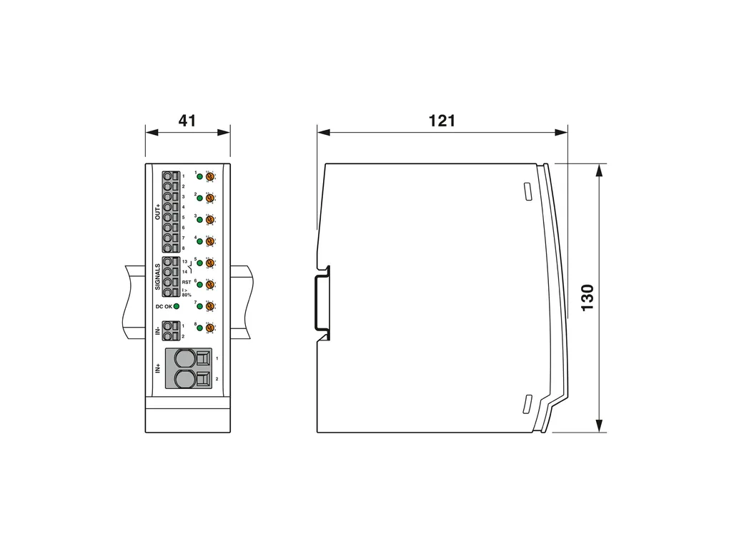
| Dimensions | Dimensional drawing: https://dam-mdc.phoenixcontact.com/rendition/156443151564/935cdde00c7c9d4cba53a37b52925243/-S204x204-FJPG Width: 41 mm Height: 130 mm Depth: 121 mm (incl. DIN rail 7.5Ãmm) |
| Material specifications | Material: PC PA 6.6 PC PBT-FR17 POM Flammability rating according to UL 94: V-0 |
| Environmental and real-life conditions | Ambient conditions Degree of protection: IP20 Ambient temperature (operation): -25°C ... 70°C (Startup at -40ÃC type-tested) -25°C ... 65°C (for UL 2367) Ambient temperature (storage/transport): -40°C ... 80°C Altitude: ââ°¤ 6000 m (amsl) Humidity test: 240 h, 95 % RH, 40°C Shock (operation): 30g (IEC 60068-2-27, Test Ea) Vibration (operation): 5ÃHzÃ...Ã24.9ÃHz (AmplitudeÃñ1.6Ãmm; in accordance with IEC 60068-2-6, Test Fc) 24.9ÃHzÃâ⬦Ã150ÃHz (AccelerationÃ4g; in accordance with IEC 60068-2-6, Test Fc with additional resonance frequency testing in accordance with DNV GL) |
| Approvals | UL approval Identification: UL/C-UL Listed UL 508 UL Recognized UL 2367 UL ANSI/ISA-12.12.01 Class I, Division 2, Groups A, B, C, D (Hazardous Location) Shipbuilding approval Identification: DNV GL DNV GL data Temperature: D Humidity: B Vibration: B EMC: A Enclosure: Required protection according to the Rules shall be provided upon installation on board |
| Standards and regulations | Standards/specifications: ENÃ61000-6-2 ENÃ61000-6-3 ENÃ60068-2-6 ENÃ60068-2-1 ENÃ60068-2-2 ENÃ60068-2-78 Note: EMC ââ¬Ã¢ Immunity for industrial areas EMC ââ¬Ã¢ Emission for residential, business and commercial properties and small operations Environmental influences ââ¬Ã¢ Vibrations (sinusoidal) Environmental influences ââ¬Ã¢ Part 2-1: Tests ââ¬Ã¢ Test A: Cold Environmental influences ââ¬Ã¢ Part 2-2: Tests ââ¬Ã¢ Test B: Dry heat Environmental influences ââ¬Ã¢ Moisture and heat, constant |
| Mounting | Mounting type: DIN rail: 35 mm |
Description other products
